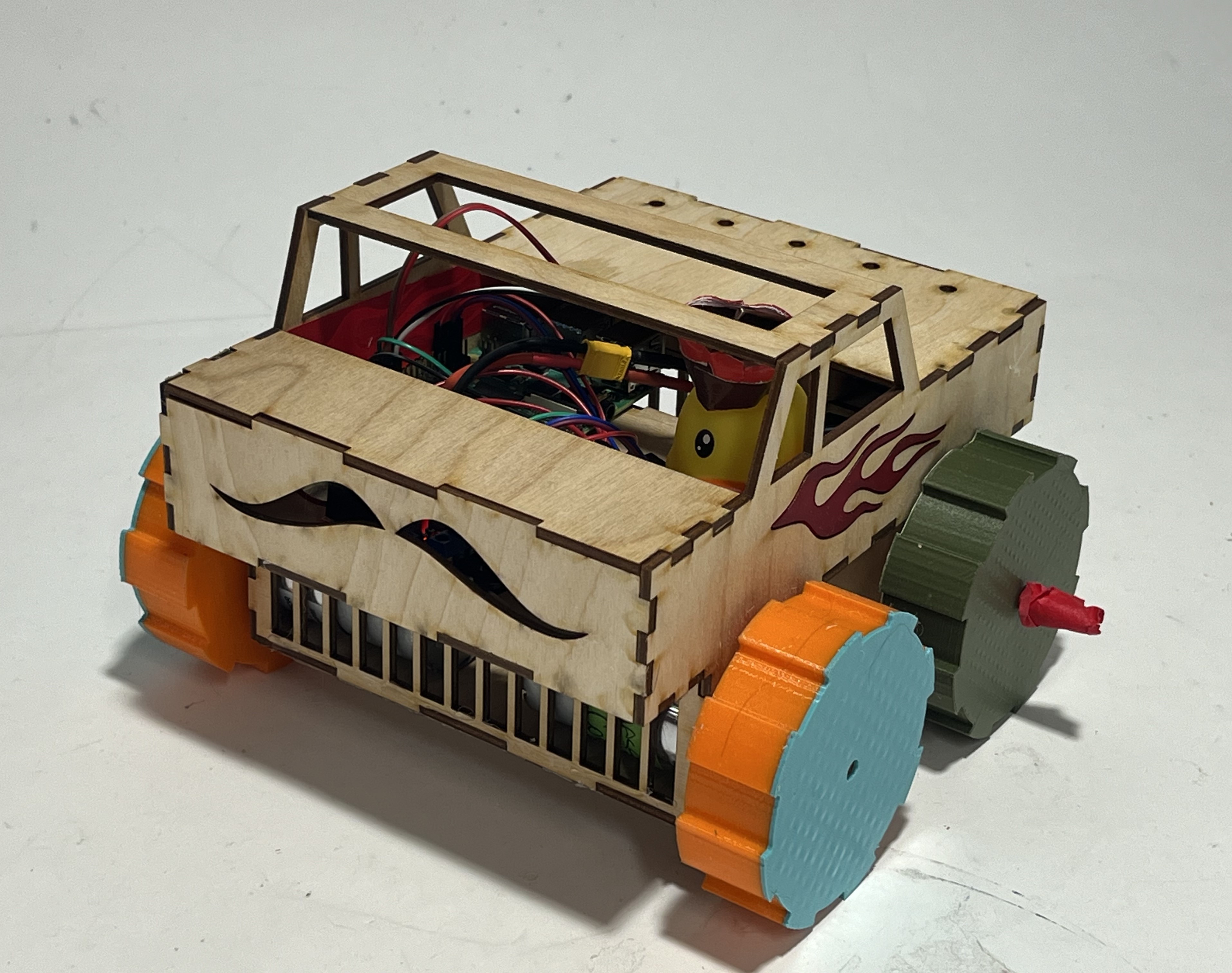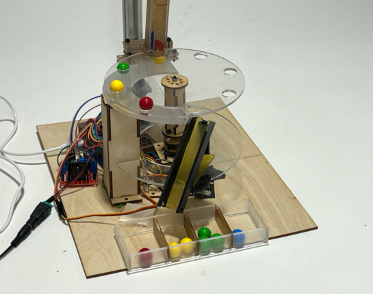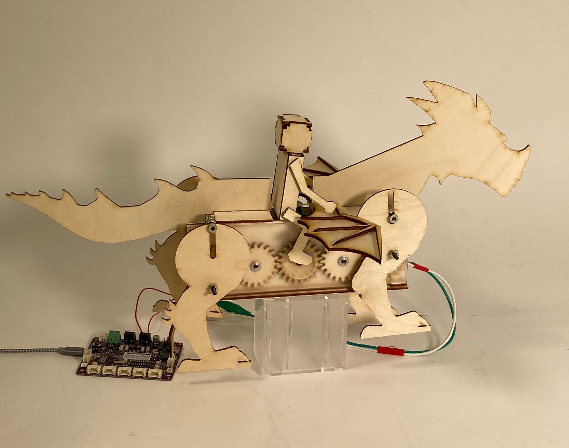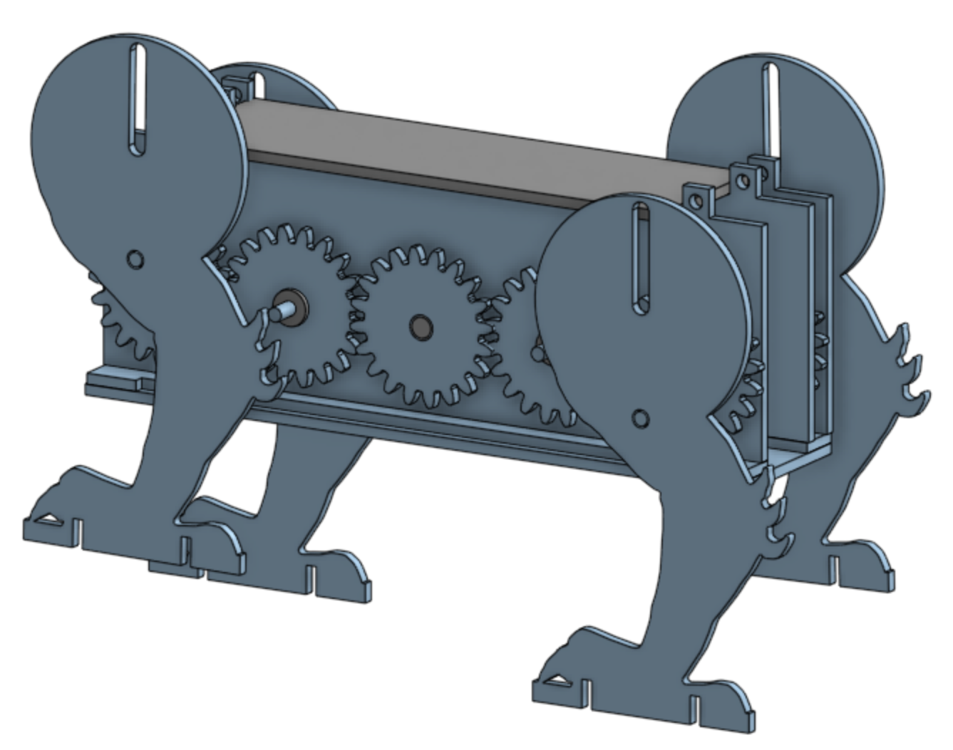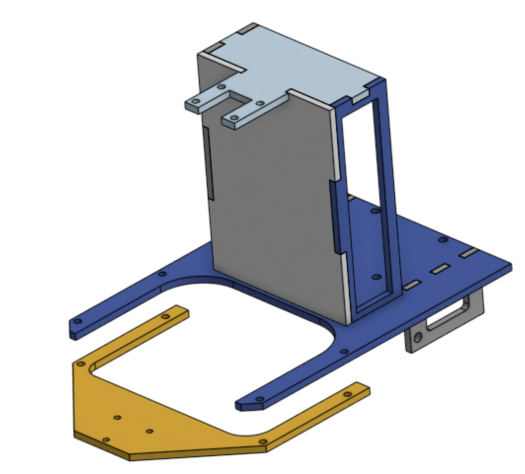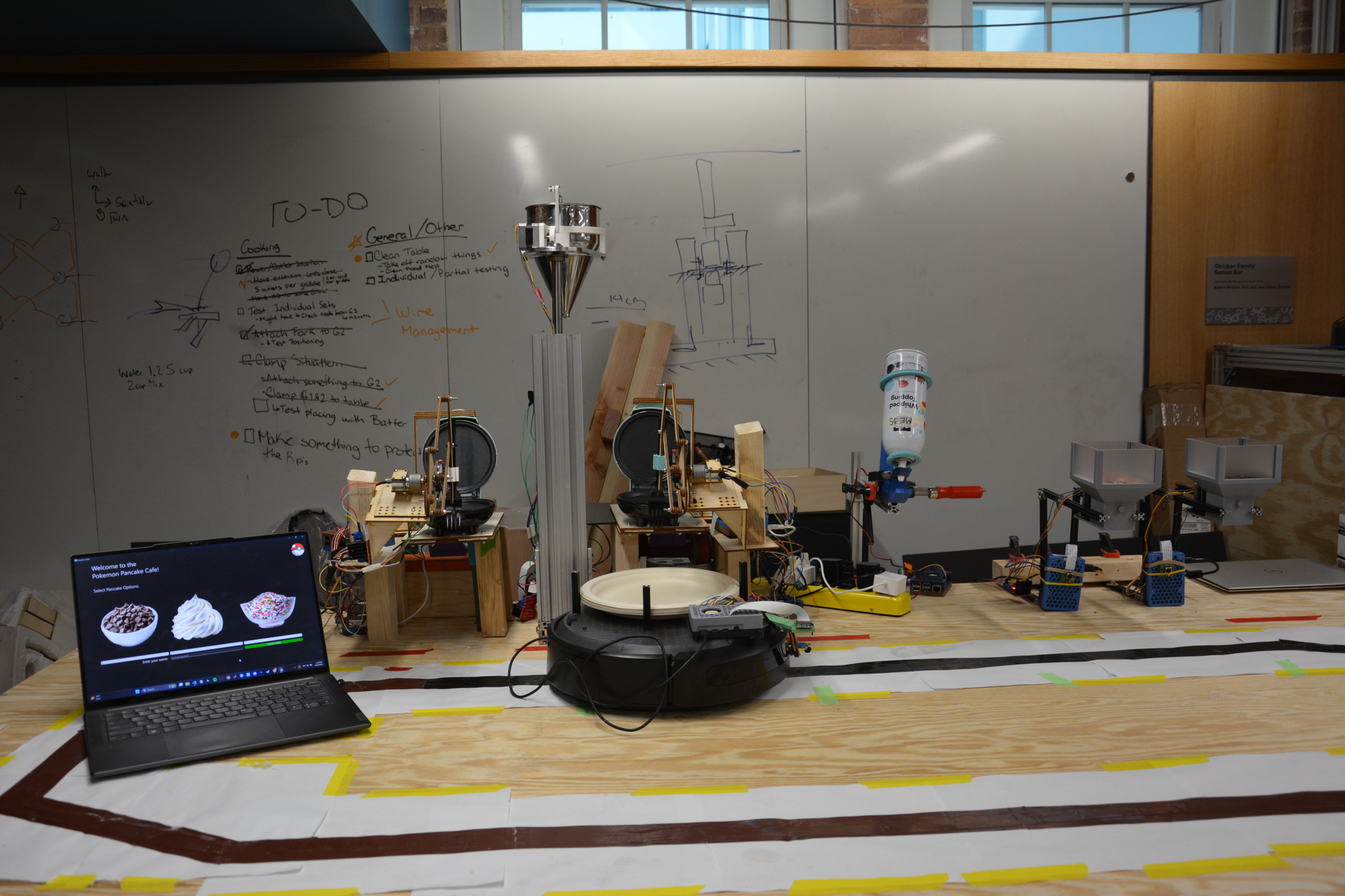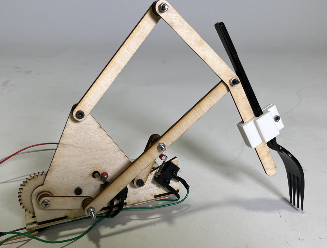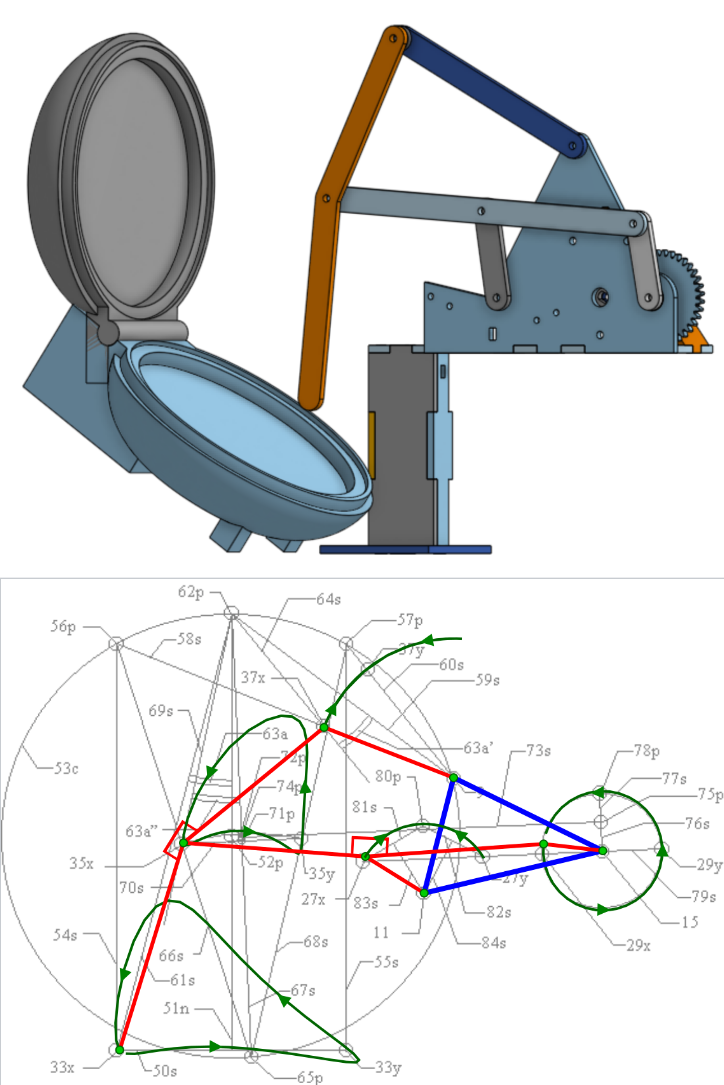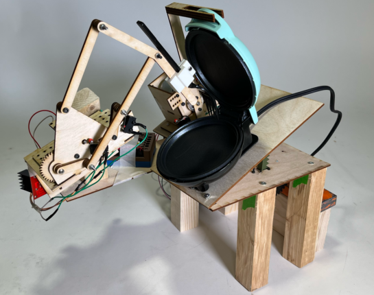
Pancake Making Robot
CAD | Linkages | Python
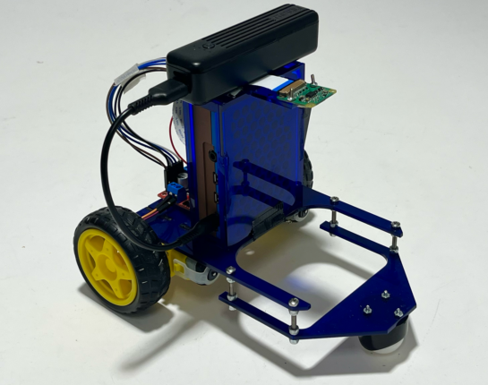
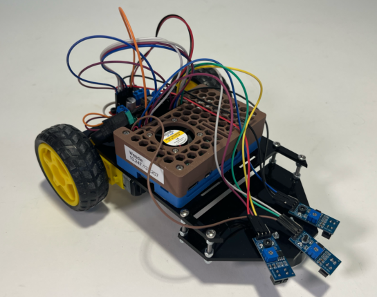
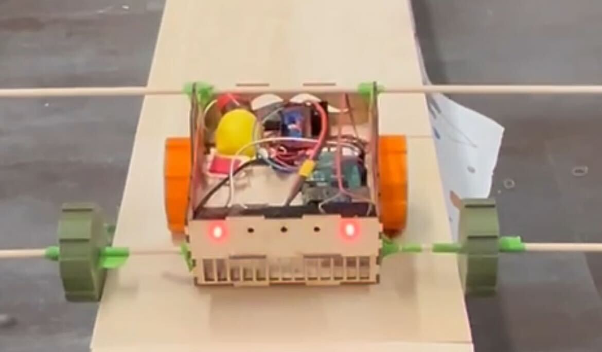
Camera Line Follower
Python | Image Processing
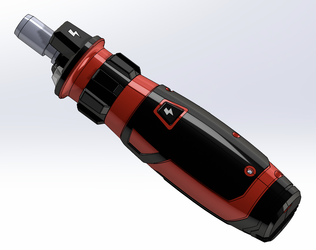
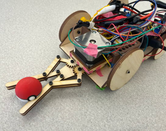
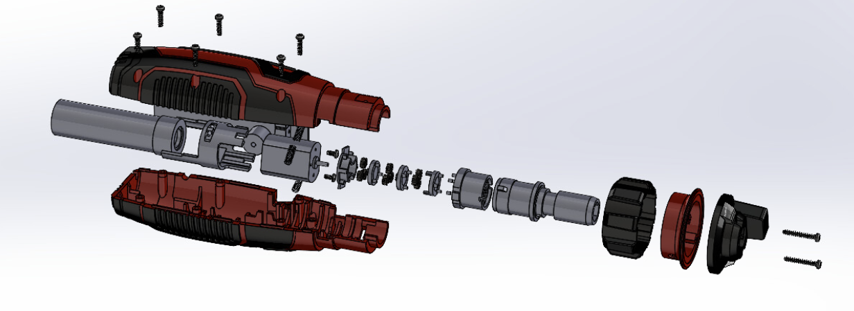
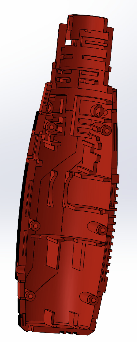
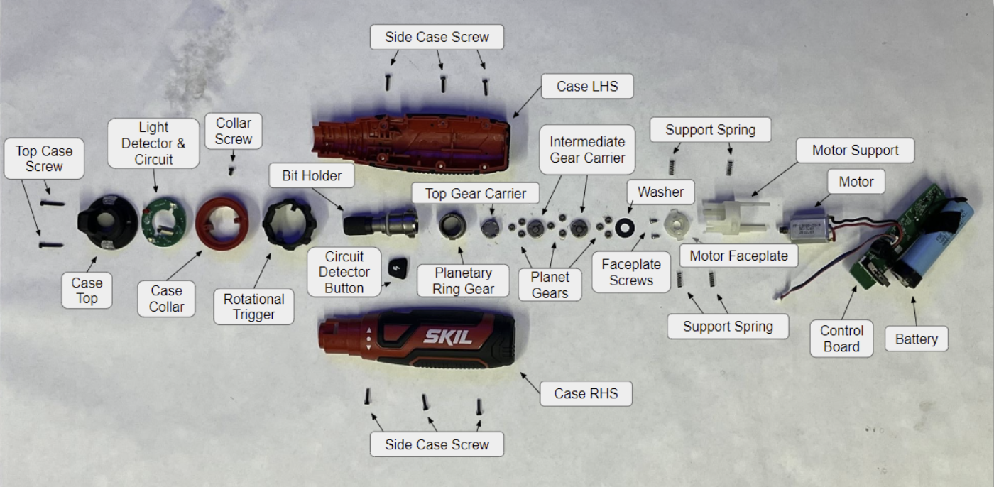
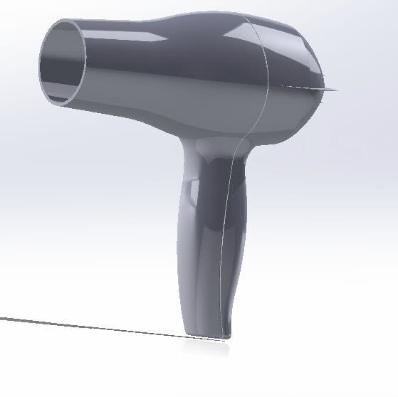
Product Teardown
Solidworks | Analysis | Teamwork